You're about to create your best presentation ever

Powerpoint Uml Template

Create your presentation by reusing a template from our community or transition your PowerPoint deck into a visually compelling Prezi presentation.

UML

Transcript: Behaviour Composite Interaction Diagram Two Views of System Model similar to the activity diagram both visualizing a sequence of activities. The difference is that the individual activity in the interaction overview diagram is pictured as a frames, which can contain interaction - or sequence diagrams Composite Structure Diagram Activity models the physical deployment of artifacts on nodes Categorized Hierarchy of UML Diagrams Diagram An Overview Diagram Group 11 Package Sequence a diagram that shows a complete or partial view of the structure of a modeled system at a specific time. - graphical representations of workflows of stepwise activities and actions with support for choice, iteration and concurrency. - diagram shows the overall flow of control. emphasizes the static structure of the system using objects, attributes, operations and relationships. Thank You! Structure Diagram Object Diagram Colimay Lizardo Macandili Mangilin State Machine Diagram shows object interactions arranged in time sequence State emphasize the things that must be present in the system being modeled emphasizes the dynamic behavior of the system by showing collaborations among objects and changes to the internal states of objects. Diagram Structure a type of static structure diagram, that shows the internal structure of a class and the collaborations that this structure makes possible. -fyrevolt Interaction Overview Diagram Unified Modeling Language Package Diagram Profile Interaction -depicts how components are wired together to form larger components and or software systems. They are used to illustrate the structure of arbitrarily complex systems. models the interactions between objects or parts in terms of sequenced messages. Communication diagrams represent a combination of information taken from Class, Sequence, and Use Case Diagrams describing both the static structure and dynamic behavior of a system. Object Diagram Timing Diagram Diagram Diagram graphical representation of a user's interaction with the system and depicting the specifications Static view <Structural> Deployment Diagram used to explore the behaviors of objects throughout a given period of time. A timing diagram is a special form of a sequence diagram. The differences between timing diagram and sequence diagram are the axes are reversed so that the time is increased from left to right and the lifelines are shown in separate compartments arranged vertically. Communication Diagram -operates at the metamodel level to show stereotypes as classes with the <<stereotype>> stereotype, and profiles as packages with the<<profile>> stereotype. The extension relation (solid line with closed, filled arrowhead) indicates what metamodel element a given stereotype is extending. Component Diagram Diagram Diagram Activity Diagram Behavior Diagram Interaction - a set of graphic notation techniques to create visual models of object-oriented software-intensive systems. Sequence Diagram emphasize what must happen in the system being modeled Diagram a significantly enhanced realization of the mathematical concept of a finite automaton in computer science applications as expressed in the Unified Modeling Language (UML) notation. Structure Timing Component a kind of interaction diagram that shows how processes operate with one another and in what order portray the different types of users of a system and the various ways that they interact with the system Dynamic view <Behavioral> Profile Diagram Use Case Diagram Use Case Diagram Diagram the main building block of object oriented modelling Diagram emphasize the flow of control and data among the things in the system being modeled. Machine Diagram - used to specify, visualize, modify, construct and document the artifacts of an object-oriented software-intensive system under development. depicts the dependencies between the packages that make up a model. Class Diagram Deployment Diagram represent both the main objects, interactions in the application and the classes to be programmed. Diagram Class Diagram Communication Diagram Overview

powerpoint template

Transcript: Nobody knows babies like we do! Quality products . Good Customer service. Every Kid really loves this store.. BABYLOU ABOUT US About Us BabyLou was established in 2004. It has been more than a decade since we started, where we have ensured to take care of every need and want of every child and infant under one roof, true to the caption “NO BODY KNOWS BABIES LIKE WE DO”. Our benchmark is to provide 100% customer service and satisfaction and continue to deliver the same with a wide range of toys, garments and Baby Products. Play and Create We Are Best 01 02 03 Block games Building Blocks help Kids to use their brain. PLAY TO LEARN in Crusing Adventures Our Discoveries Enjoy a sunny vacation aboard a luxury yacht with the LEGO® Creator 3in1 31083 Cruising Adventures set. This ship has all the comforts you need, including a well-equipped cabin and a toilet. Sail away to a sunny bay and take the cool water scooter to the beach. Build a sandcastle, enjoy a picnic, go surfing or check out the cute sea creatures before you head back to the yacht for a spot of fishing. Escape into the mountains Disney Little Princes in Also available for your Babies..... Also... Out of The World… Our reponsibility BABYLOU…. Our Responsibility All children have the right to fun, creative and engaging play experiences. Play is essential because when children play, they learn. As a provider of play experiences, we must ensure that our behaviour and actions are responsible towards all children and towards our stakeholders, society and the environment. We are committed to continue earning the trust our stakeholders place in us, and we are always inspired by children to be the best we can be. Innovate for children We aim to inspire children through our unique playful learning experiences and to play an active role in making a global difference on product safety while being dedicated promoters of responsibility towards children.

UML

Transcript: Name: Hitesh Dalmond Lecturer: Shaad Toofanee Department: Info UML/OOP 13/08/2019 Introduction 1 Unified Modelling Language (UML) is widely used throughout the software development industry and it is the standard language for specifying, visualising, constructing, and documenting software systems. Object oriented programming allows programmers to structure and organise software programs more easily as it is a programming language based on objects, not functions or procedures. OOP 2 The first step in object-oriented programming is to identify all the objects the programmer wants to manipulate and their relationship to each other, an exercise often called data modelling. Once an object has been identified, it is generalised as an object class that defines the type of data it contains and any logical sequence that can manipulate it. Each distinct logical sequence is called method. Objects communicate with well-defined interfaces called messages. #1 The concepts and rules used in object-oriented programming offer the following advantages: • The data class concept allows subclasses of data objects that share some or all of the characteristics of the main class. Called inheritance, this property of object-oriented programming imposes a deeper analysis of the data, reduces the development time and ensures a more accurate coding. • Since a class only defines the data that concerns it, when an instance of that class (an object) is executed, the code cannot accidentally access other program data. This feature of data concealment provides increased system security and avoids unintentional data corruption. #2 The concepts and rules used in object-oriented programming offer the following advantages (continued): • The definition of a class is reusable not only by the program for which it was created, but also by other oriented object programs (and, for this reason, can be more easily distributed for use in networks). • The concept of data classes allows the programmer to create any new data type that is not already defined in the language itself. Back to UML UML has three building blocks: Data - The basic building elements of model. Process - How the things are tied together. Diagrams - Graphical representation of element collection. Each UML diagram is designed to let developers and customers view a software system from a different perspective with varying degrees. It has been observed that all the UML diagrams plays vital role in software development and their importance is as follows: 1. Class Diagram. 2. Sequence Diagram. 3. Use Case Diagram. 4. Activity Diagram. 5. Component Diagram. 6. Deployment Diagram. 3

UML

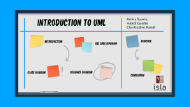
Transcript: Introduction to UML Amina Toumia Hamdi Guedes Charfeddine Hamdi UML Introduction Introduction WHAT IS UML? - UML is a standardized visual modeling language used in software engineering to represent, design, and communicate the structure, behavior, and relationships of software systems. UML DIAGrams Class diagram - It represents the static structure of a system, including classes, their attributes, methods, and relationships between classes. Class Diagram Let's understand more! Class diagram Complex Example Simple Example Elements of a Class Diagram Consider an online shop sytem with classes such as Admin, Guest, Customer, Product, Cart and Payment. Demonstrate the relationships between these classes, including associations and multiplicity. The arrows in the diagram represent associations between classes. The number next to the arrow represents the cardinality of the relationship. The attributes of each class are shown below the class name. Consider an online shop sytem with classes such as Customer, Order, Item, Orderdetail and Payment. Demonstrate the relationships between these classes, including associations and multiplicity. In UML models, an aggregation relationship shows a classifier as a part of or subordinate to another classifier. In UML modeling, a generalization relationship is a relationship in which one model element (the child) is based on another model element (the parent). In UML models, an association is a relationship between two classifiers, such as classes or use cases, that describes the reasons for the relationship and the rules that govern the relationship. - Class: Represents a blueprint for objects in a system, with attributes (variables) and methods (functions). - Association: Represents a relationship between two classes, indicating how they are connected. - Inheritance: Represents an "is-a" relationship between classes, where one class inherits properties and behaviors from another. - Aggregation/Composition: Represents a whole-part relationship between classes. - Multiplicity: Represents the number of instances of one class that can be associated with another class. USE CASE DIAGRAM - A use case diagram represents the interactions between actors and the system being modeled. - Use cases represent the functionality or actions that the system performs in response to user interactions. Elements of a Use Case Diagram Use Case Diagram - Actor: Represents a user or external system interacting with the system. - Use Case: Represents a specific functionality or action performed by the system. - Association: Represents a relationship between an actor and a use case. - Include/Extend: Represents relationships between use cases, where one use case includes or extends another. SIMPLE EXAMPLE TASK: Consider a student management system. Show use cases such as "Check attendance," "Check grades," and "Update attendance" and how they are associated with the actors. In this use case diagram: The use cases associated with the "Student" actor are "Check attendance", "Check timetable" and "Check grades". The use cases associated with the "Teacher" actor are "Check attendance" ,"Check timetable", "Check grades", "Update attendance" and "Update grades". COMPLEX EXAMPLE TASK: Consider a simple ATM system with actors like User and Bank. Show use cases such as "Withdraw Cash," "Check Balance," and "Deposit Money" and how they are associated with the actors. In this use case diagram: The "User" actor represents the ATM user who interacts with the system. The "Bank" actor represents the bank that provides the ATM services. The use cases associated with the "User" actor are "Insert Card," "Enter PIN," "Withdraw Cash," "Check Balance," and "Deposit Money." The use cases associated with the "Bank" actor are "Verify PIN," "Dispense Cash," and "Update Balance." The arrows represent the associations between the actors and the use cases, indicating the interactions between them. To indicate include and exclude relationships, we can use the following notations: Include relationship: "Withdraw Cash" includes "Check Balance": This means that when a user performs the "Withdraw Cash" use case, it includes the functionality of checking the balance before the withdrawal. Exclude relationship: "Deposit Money" is excluded from "Withdraw Cash": This means that the "Deposit Money" use case cannot be performed simultaneously with the "Withdraw Cash" use case. They are mutually exclusive. SEQUENCE DIAGRAM Sequence Diagram - A sequence diagram represents the interactions and messages exchanged between objects or components within a system. - It shows the sequence of events or steps that occur during a particular scenario or use case. Examples Sequence Diagram examples Simple EX: Sequence diagram of an Online Movie Ticket Booking System A solid line denotes a request message (i.e. a call initiated by a sender), a dashed line denotes a response message (i.e. the answer to a call). Complex ex: Sequence diagram of a purchase in

Now you can make any subject more engaging and memorable